PASSENGER COUNTER
Automatic passenger counting, door by door.
NSS's automatic passenger counting (APC) sensor combines Time-of-Flight technology mounted above the door, with Ethernet and PoE variants and native integration into ITxPT architectures.

One sensor above the door, one count for the whole fleet.
The automatic passenger counting (APC) sensor is based on Time-of-Flight (ToF) technology and mounted above the vehicle door. It detects and records, door by door, the number of passengers boarding and alighting, distinguishing between adults, children, bicycles and wheelchairs — data that's essential for schedule planning, fleet occupancy and operational reporting.
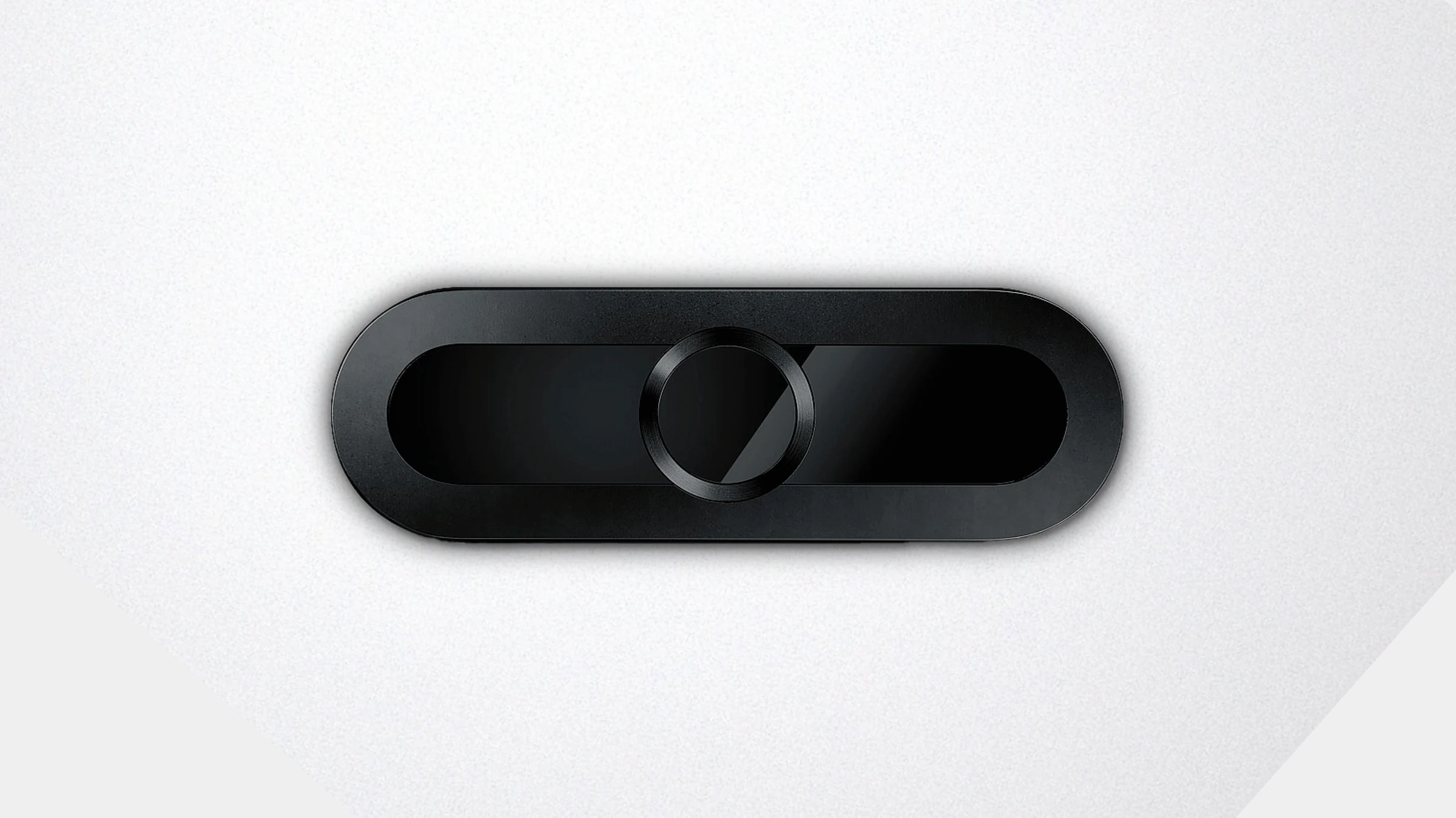
- APC counting sensor — over-door unit.
Two variants, one installation
ETH variant
Connects to the vehicle's Ethernet network via a switch or router and is powered by the vehicle — nominal 24V (16–32V), sized to the EN 50155:2021 reference in rail applications or ECE R10/ISO 16750-2 Code F in automotive applications (sensor manufacturer's design specification, no NSS test).
PoE variant
Receives power directly over the Ethernet cable (IEEE 802.3af Type 1, Class 0, 12.95W, Mode A — power over the data pairs), removing the need for an external power supply and for a 24V circuit at the door — nominal 48V, up to 57V. Average consumption 3W with counting inactive and 5W while counting (at 54V), average maximum 6W (at 48V) and a 15.4W peak.
M12 connectors on every connection
Ethernet, power and I/O connect via coded M12 connectors, resistant to vibration and water ingress — with no RJ45 exposed on board. Ethernet on D-coded M12 (1=TD+/DC+, 2=RD+/DC−, 3=TD−/DC+, 4=RD−/DC−); I/O on B-coded M12; power, on the ETH variant, on A-coded M12. Ethernet network up to 100 Mbit/s (IEEE 802.3).
I/O option — door contact
Both variants can include a dedicated M12 connector for the door contact, synchronising the start and end of counting with the door opening and closing. Bipolar input (polarity need not be observed): low level −6V to +6V, high level ±9V to ±60V with a 60V protection limit, switching up to 20Hz, 8mA at 24V (Rin 2800Ω), galvanic isolation of 60V against the I/O and 500V AC against the supply and chassis ground. Alternatively, counting starts and stops by protocol call.
Counting by category
Passengers — adults and children
Individual counting of boardings and alightings, with a configurable height threshold (default 1200mm) to distinguish adults from children.
Bicycles
Dedicated bicycle counting, with a configurable adjustment parameter between -4 and 6 depending on door width and expected volume.
Wheelchairs
Dedicated counting of wheelchair users, reported separately from the other categories.
The four figures that drive the bodywork.
The sensor comes in two parts — a sensor unit below the panel and an interface unit above it — clamped together through the cut-out by two M5×20 screws. Whoever builds the bodywork needs four numbers before cutting.
The covered door width follows from the mounting height
1800 to 2000 mm height
Maximum covered door width of 1250mm, 1400mm and 1550mm respectively.
2100 to 2300 mm height
Maximum covered door width of 1700mm, 1850mm and 2000mm respectively.
2500 mm height
Maximum covered door width of 2300mm. These are standard values — wider coverage is achievable in most cases. The sensor must be aligned with the door (IN/OUT arrows on the label) and its field of view unobstructed: an overhead panel or a stop above the mounting position shadows the counting zone and degrades the count.
On counting accuracy.
No accuracy percentage is published for this sensor, and we do not estimate one. Counting accuracy is a function of the installation — mounting height, alignment and an unobstructed field of view — not of the sensor alone. Every record carries the direction and a count-quality indicator, which is what makes it possible to judge in service whether the installation is counting well.
Integration and remote management
ITxPT protocol
Implements the standardised Automatic Passenger Counting (APC) and Module Inventory services, in the in-vehicle HTTP/XML profile and in the over-the-air MQTT profile, with automatic discovery via mDNS/DNS-SD.
IBIS-IP (VDV 301)
Besides ITxPT, the sensor speaks IBIS-IP per VDV 301 and a simple HTTP/XML integration protocol — three alternative integration paths, so the onboard network is not forced into a single one.
Data via MQTT
Sends counting results via MQTT to a local or remote broker, with automatic broker discovery via mDNS or manual IP address configuration.
Network protocols
DHCP, HTTP, HTTPS, MQTT, SNTP, SNMP, mDNS, DNS-SD, TCP/IP and UDP.
Web interface
Configuration, monitoring and firmware updates via browser, with real-time 2D/3D depth image display, available in English, French, Polish and German.
Daisy-chaining
Additional sensors can be daisy-chained via Ethernet, up to 12 units, reducing cabling in vehicles with multiple doors.
Tamper detection
The sensor detects and reports damage or obstruction to its field of view, flagged in the web interface and in the device status.
Cybersecurity
User and account management, role-based access control, certificate management and a secure firmware update procedure, with testing and rollback capability.
EN 50155:2021 — sensor manufacturer's declaration
European standard for electronic equipment in rail rolling stock. It is a catalogue requirement from the sensor manufacturer for the ETH variant in rail applications — NSS holds no test report to this standard for this product.
ECE R10 / ISO 16750-2 Code F — sensor manufacturer's declaration
Regulation and standard for the electrical conditions of equipment in road vehicles, as stated by the sensor manufacturer for the ETH variant in automotive applications. The R10 approval held by NSS covers the destination displays and the INSAT — not this product.
IEC 60825-1:2014 — design specification
The sensor is classified by its manufacturer as a Class 1 laser device, not hazardous under normal conditions of use. It is a catalogue specification from the sensor manufacturer, not a test report held by NSS.
IP65 / IK06 — design specification
Protection rating against dust, water and mechanical impact as stated by the sensor manufacturer for a correctly mounted unit — design specification, with no test report held by NSS.
EN 45545-2 · EN/IEC 61373 · EN 50121-3-2 · 2014/30/EU — sensor manufacturer's declaration
Fire behaviour, shock and vibration, and electromagnetic compatibility for rolling stock — catalogue standards from the sensor manufacturer. NSS holds no test report or certificate to these standards for this product.
UN ECE R118 · IEC/EN 60721-3-5 · RoHS · REACH · CLP · 2006/25/EC — sensor manufacturer's declaration
Burning behaviour of interior materials, environmental conditions and restriction of hazardous substances — catalogue standards from the sensor manufacturer. NSS holds no test report or certificate to these standards for this product.